Aruba Control Plane Security and the AP-203H

Here’s a useful little tidbit for anyone with an Aruba OS 6.5 environment wanting to enable control plane security with some AP-203H on the network.

(EDIT: This also applies to AOS8 where CPsec is now enabled by default. Whilst the AP-203H is quite a dated now, there may be some still around and you will experience these issues when migrating from AOS6/6.5 to AOS8)

With Aruba campus APs all traffic between users and the controller is encrypted (probably) by virtue of the Wi-Fi encryption in use being between the client and the mobility controller, rather than being decrypted by the AP. So unless you’re using an open network all your client traffic is encrypted until it pops out of the controller. Lovely.

Control plane traffic, the AP talking to the controller, is not. This isn’t usually a problem as we mostly trust the wires (whether we should or not is another matter).

In many Aruba controller environments all the user traffic is tunneled back to the controller in our data centre, which works very well especially when users are highly mobile around a campus.

However it’s also possible to bridge an SSID so the AP drops the traffic on a local vlan. This is desirable in some circumstances, one real world example being a robotics research lab needing to connect devices to a local subnet. In order to enable this you first have to switch on control plane security.

Switching CPsec on causes all APs to reboot at least twice so on an existing deployment it leads to 8-15 minutes of downtime. I switched CPsec on this morning for our network with approximately 2500 APs, it was a tense time but went well…. mostly.

I’d read stories of APs with a bad trusted platform module being unable to share their certificate with the controller. We have a lot of APs from many years old to brand new and even a low percentage failure rate would present a problem.

In the end two APs failed, with lots of TPM initialization errors. However all our AP-203H units failed to come back up and the controller process logs started showing things like this:

Sep 4 07:57:37 nanny[1399]: <303022> <WARN> |AP <apname>@<ip_addr> nanny| Reboot Reason: AP rebooted Wed Dec 31 16:01:41 PST 1969; Unable to set up IPSec tunnel to saved lms, Error:RC_ERROR_CPSEC_CERT_REJECTED

It took a little while to become clear just one model of AP was affected and it was all of them.

A bit of time with Aruba TAC later and it transpires it’s necessary to execute the command: crypto-local pki allow-low-assurance-devices 

This needs to be run on each controller separately, and saved of course.

The command is detailed as allowing non-tpm devices to connect to the controller. I’m not entirely clear what’s special about the AP-203H, presumably it doesn’t have a TPM, yet it does have a factory installed certificate. We also have some AP-103H units, which don’t have a TPM but they work just fine with a switch-cert. I suspect this is a bug in the firmware and Aruba OS is treating the 203H as if it has a TPM but as it doesn’t everything falls apart.

Clearly if you want the maximum possible security, allowing low assurance devices is presumably going to raise eyebrows. In our case we’re happy with this limitation.

May this post find someone else who one day searches for RC_ERROR_CPSEC_CERT_REJECTED ap-203h 
Where’s the data?

On my quest to learn this week I had the privilege to attend Peter Mackenzie’s Certified Wireless Analysis Professional class. When a colleague and I attended Peter’s CWNA class a couple of years ago he suggested that CWAP should the be next port of call after passing the CWNA exam. Initially I thought that was mainly because he wrote the book (and an excellent book it is too) but actually CWAP goes deeper into the protocol and builds an even better foundation for an understanding of how WiFi works.

Most people who’ve dabbled in networking are familiar with Wireshark. It’s a fantastic tool, and a great way of troubleshooting problems. With packet capture you can prove that client isn’t getting an IP address because it isn’t doing DHCP properly if at all, rather than it being a wider network issue…

Wired packet capture is usually easy. Mirror a port on a switch, put an actual honest to goodness old school hub in line (if you have one and can tolerate the lower bandwidth during capture), or if you have the resources get a fancy tap or dedicated capture device such as the Fluke Onetouch. Usually we have one of these methods available but for Wi-Fi it’s not quite so easy.

Mac users have these fantastic tools available, and there are good options for Linux users but for Windows folk life can be tough and expensive.

Wi-Fi drivers for Windows tend not to expose the necessary level of control to applications. So you’re left needing a wireless NIC with a specific chipset for which there’s a magic driver, or getting hold of an expensive dedicated capture NIC.

There is one option that I’ve played with in the form of Tarlogic’s Acrylic WiFi. This affordable software includes a ndis driver that interfaces with the Wi-Fi NIC and presents monitor mode data to applications. Analysis within Acrylic is fairly poor but it will save pcap files and it’s possible to use the Acrylic driver directly in Wireshark.

The problem is that many new drivers don’t interface with ndis in Windows as things used to so as a result there’s a shrinking number of available Wi-Fi NICs that still work.

Some time ago I bought an Asus AC53 USB NIC which is on the Acrylic supported list and it is possible to install the old windows8.1 drivers on windows 10. However this doesn’t support DFS channels, which is a problem because we use DFS channels.

Fear not though it is, just about, possible to make this work. The Netgear A6200 uses the same Broadcom chipset and supports DFS channels. Once installed I was able to select the netgear driver for the Asus device and sure enough it works.

Which is a long lead in to this little tidbit, a key take away from Peter’s course this week.

When looking at a wireless capture it’s important to remember you might not be seeing all the information. Physical headers are stripped off by the hardware of the Wi-Fi interface, so you can’t see those. Wi-Fi does certain things with physical headers only, such as Mu-Mimo channel sounding and aspects of this are therefore not visible to a protocol analyser.

It probably goes without saying that you can’t see encrypted data, but you can usually see that it’s been transmitted… Unless your wireless interface can’t decode it.

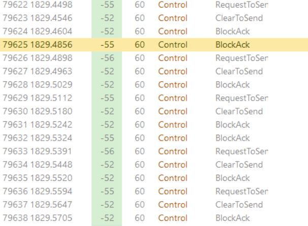
Let’s say, for example, your AP is using a 40MHz DFS channel and the capture setup you’re using can’t be configured to use 40MHz channels. In this scenario, because management and action frames are all transmitted on the primary 20MHz channel you can see these just fine, yet all the higher rate data frames that take advantage of the full 40MHz just disappear.

The result looks a bit like the picture here… A client sends RTS, the AP responds CTS and the next thing is a block acknowledgement but no data.

It’s sometimes possible to see the data transfer betrayed in the time between the packets but here, because the data rate is high and the traffic is light, it’s not particularly apparent.

I’m particularly looking forward to spending more time digging into protocol analysis and hopefully getting some better tools.

2.4GHz Channels and a four channel plan

EDIT – The conclusions of this article no longer apply to most environments as Bluetooth beacons have been arranged to avoid channels 1, 6 & 11 but will cause problematic interference with other 2.4GHz channels discussed here.

Many people say 2.4GHz is dead and whilst I view it as ‘best effort’ it isn’t going away and needs to be supported so I want it to be the best it can be. I use a four channel plan on our campus and my colleagues were recently informed this should never be done which inspired this post to explain the decision. This is quite lengthy but hopefully understandable. All comments and criticism welcome.

Continue reading →

Wifi Design Cycle

I’m in the process of carrying out wifi improvement works on the campus, so I thought I’d write some pieces about our wifi equipment lifecycle and the processes I’m following.

Initial Survey
Pretty much everywhere has some wifi coverage. I’m therefore starting with an initial survey to find out what we currently have and inform what we need to change. Even if I know the coverage is terrible and I need to just start again, this survey is necessary to provide before and after documentation. It also shows how RF propagates through the building, which can help identify troublesome areas of attenuation that don’t show up on the plan. I try to identify where the available data points are at this stage, though it can be hard to be thorough about this.

Design
The design stage is predictive, though it’s sense checked using the initial survey information.

Deploy
Once there’s a new design, this gets deployed – this can be where some compromises occur as it turns out that ceiling cavity contains asbestos, or one of these data cables is damaged. Deployment is sometimes going to be done by me, sometimes by a contractor.

Validate
A repeat of the initial survey – validate the coverage is as expected, that APs are using sensible channels and we don’t have a Co-Channel Interference disaster, that 2.4GHz radios are on a sensible power setting or disabled as is appropriate. At this point there’s a loop back to design in the flowchart. If things are not looking as expected it’s back to the drawing board to find a remedy, then deploy physical or config changes and survey the area again. Recently I’ve carried out validation surveys in areas where I know an install compromise was made because the building structure wasn’t quite as expected. It was strangely satisfying to discover the original design was sound and the new AP position wasn’t working, so I had to come up with a different option.

Monitor
This is an ongoing process, but it’s worth confirming the throughput for group of APs is in the expected range (hasn’t dropped horribly for a building) and retransmissions are at acceptable levels. We use Aruba Airwave which makes it easy to group APs into an area for graphing of basic metrics. When wifi is improved in a building we expect to see an increase in client count and throughput but that isn’t always the case. Improving coverage in a lab means tablets can be used for note taking; that might be one or two more devices, not something that’s going to impact the graph.

I also talk to the users. Let them know there’s been a change, if they don’t already know. Ask for feedback and encourage them to tell you if there’s an device they need to use that doesn’t work so well in some parts of the building. Hopefully the design and validation accounts for this, but…..  I’ll more to day about that in another post.