VLANs on Mikrotik CRS

Mikrotik switches and routerboards are incredible value and, equipped with the very powerful RouterOS, remarkably capable however I’ve never found RouterOS the most intuitive to configure. I’ve personally found doing the simple things, such as setting up VLANs with trunk and access ports, really confusing.

With that in mind, here’s a quick run down on how to do just that in the CLI.

Some useful commands:

  • add – adds a config item
  • remove – removes a config item by index number – e.g. remove 3
  • set – sets a variable on an existing config item – e.g. set 3 pvid=99
  • export – lists the config at the current context
  • print – lists properties of the current context including the index of each config item

I have always found RouterOS config to be confusing but it’s actually very readable once you understand the principle of operation. It’s broken down into contexts in a logical structure. Here we’re configuring a layer 2 switch so doing almost everything within the bridge context /interface bridge. This is where layer2 config lives. The contexts are navigated a bit like a file structure with / being the root. Make use of the print and export commands to understand what config exists.

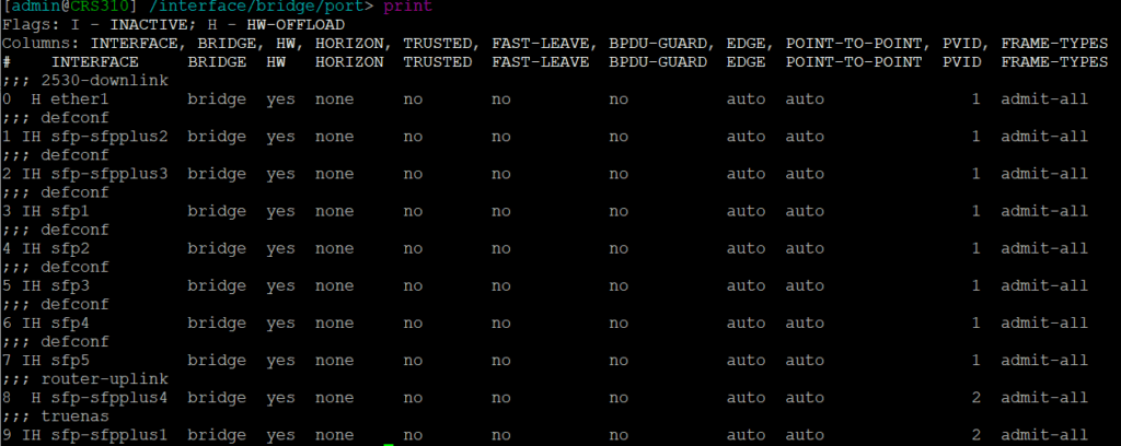
A default configuration will probably have been applied that defines a bridge with all ports added and a default IP address assigned to the bridge for initial remote config. To change a variable of an existing config line use the set command. You need to know the index number, starting at 0. To get this use the print command when in the appropriate context. For example below is the print output from the /interface bridge port context. Based on this, to change the PVID to 99 on port SFP1 use the command: set 3 pvid=99
The Config
This is a simple config with three VLANs: 2 (Management), 3 (IOT), and 10 (WLAN). The management VLAN is untagged on some ports, there is an SVI/VLAN interface with an IP address used for switch management. The other VLANs are tagged. Not all ports are in use and though they are added to the bridge and enabled, there is no VLAN config applied.

The following actions need to be performed:

  • Create a bridge – the first bridge will refer to the switch chip (if available) do not create additional bridges as these will be in software, switching traffic through the CPU
  • Assign ports to the bridge
  • Create VLANs in the bridge & assign to ports as tagged or untagged as required
  • Create a VLAN interface for management
  • Assign an IP address to the management VLAN interface
  • Ensure VLAN filtering is enabled on the bridge
  • Set the PVID/native VLAN on ports as required

Create/edit a bridge (note this was done by autoconf and edited with set 0 vlan-filtering=yes)
/interface bridge
add name=bridge protocol-mode=none vlan-filtering=yes

Assign ports – all ports are assigned to the bridge by defconf. You can either edit the existing entry or remove and add with the desired config. Here you can see sfp-sfpplus1 and 4 have been assigned a PVID of 2 – the default PVID=1 does not show in the config.
/interface bridge port
add bridge=bridge comment=2530-downlink interface=ether1
add bridge=bridge comment=defconf interface=sfp-sfpplus2
add bridge=bridge comment=defconf interface=sfp-sfpplus3
add bridge=bridge comment=defconf interface=sfp1
add bridge=bridge comment=defconf interface=sfp2
add bridge=bridge comment=defconf interface=sfp3
add bridge=bridge comment=defconf interface=sfp4
add bridge=bridge comment=defconf interface=sfp5
add bridge=bridge comment=router-uplink interface=sfp-sfpplus4 pvid=2
add bridge=bridge comment=truenas interface=sfp-sfpplus1 pvid=2

Create VLANs on the bridge (L2) and assign to ports as tagged/untagged. VLAN is tagged/untagged using a comma separated list of interfaces. Note the management VLAN is tagged to the bridge itself as well as any ports – this makes the VLAN available to the CPU
/interface bridge vlan
add bridge=bridge comment=management tagged=sfp-sfpplus3,ether1,bridge untagged=sfp-sfpplus1,sfp-sfpplus4 vlan-ids=2
add bridge=bridge comment=WLAN tagged=ether1,sfp-sfpplus3,sfp-sfpplus4 vlan-ids=10
add bridge=bridge comment=IOT tagged=ether1,sfp-sfpplus3,sfp-sfpplus4 vlan-ids=3

Create the VLAN interface/SVI – this is the layer3 interface for a VLAN. You need to define this in order to apply an IP address.
/interface vlan
add interface=bridge name=management vlan-id=2

Apply an IP address to the management VLAN interface. If you have a defconf IP address configured on the bridge you will need to remove this.
/ip address
add address=172.20.0.4/24 interface=management network=172.20.0.0

Lastly here’s a bit of general system config setting the hostname, DNS and NTP sync
/ip dns
set servers=172.20.0.1
/ip route
add dst-address=0.0.0.0/0 gateway=172.20.0.1
/system identity
set name=CRS310
/system ntp client
set enabled=yes
/system ntp client servers
add address=0.uk.pool.ntp.org

The one place I got stuck for longer than I’d like to admit was having to set a PVID in a different place to VLAN tagging. With this config structure I initially assumed setting a bridge VLAN as untagged on a bridge port would define that as the PVID for the port – it does not.

The complete config:
/interface bridge
add admin-mac=F4:1E:57:7C:3E:F0 auto-mac=no name=bridge protocol-mode=none \
vlan-filtering=yes
/interface vlan
add interface=bridge name=management vlan-id=2
/port
set 0 name=serial0
/interface bridge port
add bridge=bridge comment=2530-downlink interface=ether1
add bridge=bridge comment=defconf interface=sfp-sfpplus2
add bridge=bridge comment=defconf interface=sfp-sfpplus3
add bridge=bridge comment=defconf interface=sfp1
add bridge=bridge comment=defconf interface=sfp2
add bridge=bridge comment=defconf interface=sfp3
add bridge=bridge comment=defconf interface=sfp4
add bridge=bridge comment=defconf interface=sfp5
add bridge=bridge comment=router-uplink interface=sfp-sfpplus4 pvid=2
add bridge=bridge comment=truenas interface=sfp-sfpplus1 pvid=2
/interface bridge vlan
add bridge=bridge comment=management tagged=sfp-sfpplus3,ether1,bridge untagged=\
sfp-sfpplus1,sfp-sfpplus4 vlan-ids=2
add bridge=bridge comment=WLAN tagged=ether1,sfp-sfpplus3,sfp-sfpplus4 \
vlan-ids=10
add bridge=bridge comment=IOT tagged=ether1,sfp-sfpplus3,sfp-sfpplus4 \
vlan-ids=3
/ip address
add address=172.20.0.4/24 interface=management network=172.20.0.0
/ip dns
set servers=172.20.0.1
/ip route
add dst-address=0.0.0.0/0 gateway=172.20.0.1
/system clock
set time-zone-name=Europe/London
/system identity
set name=CRS310
/system ntp client
set enabled=yes
/system ntp client servers
add address=0.uk.pool.ntp.org

Core switching and routing

Put simply not all switches equal. This should be obvious, there’s a reason all vendors have a wide range of options at different prices, but… what happens if you get the wrong kit?

The most obvious metric is the device throughput – how much traffic can be switched or routed by the hardware – you simply want to avoid bottlenecks where possible and that’s straight forward enough. If you have a 10Gb internet connection and plug it into a 1Gb switch port, you now have a 1Gb internet connection. I have seen that done and the ticket raised “why are we not getting the speed we’re paying for”.

What I’m more interested in is table sizes.

Switches have MAC tables and routers have ARP tables (IPv4) and Neighbour tables (IPv6) and, yes, these are often the same physical devices.

The MAC table records the MAC addresses seen on each port and is key to switching traffic efficiently, sending frames only to the appropriate port. The ARP and Neighbour tables match an IP address to a MAC address so incoming packets can be forwarded. If these tables are filled the router may drop traffic for any addresses it doesn’t know.

Put simply the network equipment needs to have sufficiently large table sizes to accommodate the number of network clients. When this is not the case, things stop working and often in unpredictable ways; some clients will work just fine, others won’t work at all. Maybe someone was happily on line at 10am but at 10:11am when they try again, nothing is working.

This is a common problem with cheap gear. The ISP router might let you setup a really large subnet but it may only be able to handle 50 clients at once due to memory limitations. It’s weird to refer to network gear as “prosumer” but there’s plenty of more affordable kit out there that will take the config you want without delivering what you need.

With serious enterprise gear the table sizes are often really big but the devil is in the detail. A switch might have full layer3 support but be weighted towards layer2 tables with a HUGE MAC table supporting hundreds of thousands of MAC addresses but perhaps a much smaller layer3 table of only 16,000 or so. Because you usually want one or the other the switch may allow you to configure which table is larger.

Here’s a little tale from personal experience. Consider a university campus wireless network which could see over 20,000 clients. As part of a general upgrade the routing was moved from an aging Procurve 5400 switch to a Comware 5900. Everything was great until, a couple of weeks later, term started and the client numbers climbed past 16,000 at which point the calls started coming in about the Wi-Fi not working.

That number was very suspicious and very quickly the recent changes were looked at. We found the new 5900 switch had a ARP table limit of 16,384 vs the MAC table limit of 131,072. This was a switch optimsed for layer2 switching in the data centre, lots of VMs and therefore lots of MAC addresses. But the small ARP table made it unsuitable for our use case. We didn’t know this until it became painfully obvious.

Finally a word of warning on IPv6. Table sizes need to be much larger for the same number of clients. With IPv4 each client will have one address. With IPv6 clients will have multiple addresses. IPv6 addresses also take up more space so the same physical memory will handle far fewer IPv6 table entries vs IPv4.

Understanding the capacity of your equipment is just as important as the functionality.

Getting DHCP right

The second in a short series on the wider network services we need to get right in order to offer a good user experience to our Wi-Fi clients – first I mused about DNS, this time it’s Dynamic Host Configuration Protocol or DHCP for IPv4.

Put simply DHCP is what assigns your device an IP address when it joins a network. I’m not going into detail on how to configure it, the focus here is what I’ve seen go wrong in the real world.

Ensure your IP address space and DHCP scope is large enough for the intended number of clients. For example a coffee shop with a peak of 20 clients would be just fine using a /24 subnet that allows for a total of 253 clients (after accounting for the router address) whereas a 17,000 seater stadium would need a substantially larger subnet. Don’t short change yourself here, make sure there’s plenty of room for growth.

Pool exhaustion due to long lease duration. When the DHCP server runs out of IP addresses to hand out, that’s known as pool exhaustion. Consider the coffee shop with an ISP provided router which offers an address in a /24 subnet. That’s fine for the first 20 customers of the day, and the next 20, and so on, but a busy shop could soon have a lot of people come through and if enough of them hop onto the network the DHCP pool could run out – this is especially the case if the pool isn’t the full 253 addresses but maybe only 100. The simple fix for this is to set a lower lease time for DHCP, 1 hour would likely be sufficient but beware of short lease times having an impact on server load in some circumstances.

The client needs to be able to reach the DHCP server. A common deployment of captive portals moves the user into a different role after authentication. I have encountered networks where the authenticated role blocked all RFC-1918 addresses as a catch all to prevent access to internal services however this would prevent the client from renewing an IP address. Much unpredictability ensued. The solution was simply to allow DHCP traffic to reach the DHCP servers.

DHCP server hardware capacity. DHCP can get really complicated and tied into expensive IPAM products such as infoblox. For most deployments this isn’t necessary and the hardware requirements are usually not significant enough to be a concern. However this can be context dependent. A busy network with lots of people constantly coming and going likely has a very low peak DHCP request rate. A stadium network where lots of people arrive very quickly may see peak demand that requires a little more horsepower – as with DNS, keep an eye on the server load to understand if hardware limits are being reached. In practice very modest hardware can meet the DHCP demand of many thousands of users.

Multiple server syncronization is where more than one server shares the same pool, best practice in larger deployments for redundancy but it’s something I have seen go wrong with the result the same IP address is offered to more than one client. Fixing this is getting too far into the weeds and will be implementation specific, it’s enough to know that it absolutely shouldn’t happen and if the logs suggest it is, that’s a serious problem that needs someone to fix it.

The DHCP server simply stops working. Yep, this can and does happen. It’s especially a problem in some of the more affordable hardware solutions such as ISP provided routers. I encountered a Mikrotik router being used for DHCP on a large public network and from time to time it would just stop issuing IP addresses to random clients before eventually issuing no leases at all. A reboot always resolved this and I’m sure newer firmware has fixed this. There was often a battle with the owner of this to get them to restart it because “it was routing traffic just fine” and, yes, it was. It just wasn’t issuing IP address leases any more.

Why is it always DNS?

When we’re working on the Wi-Fi it can be easy to overlook some of the basic network services that are essential to client connectivity. These might be managed by someone else or just not your bag if you’ve spent all your time learning the finer points of 802.11. So here’s the first of a few short pieces looking at these elements of building a good Wi-Fi network, focussing this time on Domain Name System or DNS.

Put simply DNS is the thing that resolves a human friendly wordy name such as wifizoo.org into an IP address such as 178.79.163.251 (IPv4) and 2a01:7e00::f03c:91ff:fe92:c52b (IPv6).

When DNS doesn’t work the whole network can appear to be down. No DNS means your browser can’t resolve google.com to an IP address so can’t send any requests. Many network clients check a test web server can be reached to confirm internet connectivity – if it can’t be resolved the client will report no internet… Poor DNS performance can make the fastest network appear slow to the end user.

What I’m stressing is DNS needs to work and it needs to be responsive and reliable.

What I’ve seen go wrong

Right size the server – Too many clients hitting a server with insufficient resources is a bad time that you will likely only see at peak usage. A coffee shop with 20 clients is fine with the ISP router as the local DNS server. A stadium with 10,000 clients needs a caching DNS server capable of handling the peak requests per second. Be aware of what your DNS server is and what else the server might be doing. Be aware of system resource utilization (CPU, memory, etc) at peak times to understand if the hardware is reaching capacity.

Have more than one DNS server. Like right sizing, this depends on context. Again a coffee shop will have a single DNS server in the form of the ISP router, which is a single point of failure no matter what. A larger network with redundant switching and routing should have at least two DNS servers issued to clients and these should be in separate locations – you’re aiming to ensure DNS is available in the event of a failure somewhere. I have encountered a situation where two DNS servers were VMs running in the same DC which lost power. Someone forgot to pin the servers to specific hosts.

Public DNS servers rate limiting – The network became slow and unreliable at peak times but airtime utilization was not the problem. Say you decide to use a public DNS such as Google’s 8.8.8.8 or Cloudflare’s 1.1.1.1 on a public Wi-Fi network that sends all outbound traffic from a single NAT’ed public IP address. You run the risk of the DNS being rate limited. I’ve seen this happen and there is very little to no documentation about thresholds. Use either an internal server or a paid DNS service for public networks, which can also bring benefits of simple filtering access by reputation (adult, gambling, etc) and known malware domains.

Monitor DNS on public Wi-Fi. Use something like HPE Aruba UXI or Netbeez that sits as a client on the network and runs regular tests. This can provide visibility into problems like high DNS latency or failure and log this against a time stamp that will help diagnose issues related to overloaded or rate limited DNS.

Upstream servers are rubbish. Lots of complaints about “slow” network but throughput and latency was always fine. Issue was a poorly performing upstream DNS which took long enough to resolve anything not in the local server cache that it would often time out. For internal DNS servers consider what is being used upstream. If your high performing local DNS server is forwarding requests it can’t answer to a poorly performing ISP DNS server you’ll still have a bad time.

My personal recommendation for any public Wi-Fi solution is to use a local caching DNS server. Unbound DNS is a good option. This is easily deployed on linux. It’s built into opnsense open source firewall/router, which is an easy way to deploy if you just want an appliance. I will keep coming back to opnsense for other elements of this series as it’s often a great solution. The default Opnsense configuration of Unbound will use the DNS root servers to locate authoritative answers to queries. You can also forward requests to specific upstream servers.

It’s key to understand the client experience. There can be a temptation to see hundreds or thousands of clients on the network and plenty of data moving as justification to minimize user complaints of poor performance – however it might just be that DNS is letting down your excellent RF design.

ClearPass Guest DoB Regex

I don’t like the ClearPass date/time picker because it picks a time whether you want to or not, which is confusing, and if you’re as old as I am having to click back to find the correct year is tiresome.

Here’s a handy regex validator for UK format date of birth. This is an amalgamation and tweak of several expressions I found when setting up a captive portal for a client.

This format assumes day month year, as commonly used in the UK. It will validate against double or four digit years and allow either dd/mm/yy or dd-mm-yy.

The aim was to be as flexible as possible in the format used.

Clearly it will also validate if someone puts in a date of 4th September 1984 as 09/04/84 so we’re not being super precise about things but this is was deemed good enough and it’s less likely a UK user would use the wrong format.

Although the expression is less prescriptive than this, a validation error was written for clarity so the user it given an example that will validate.

/^(3[01]|[12][0-9]|0?[1-9])(\/|-)(1[0-2]|0?[1-9])\2([0-9]{2})?[0-9]{2}$/

How to do Wi-Fi in your home

tl;dr: stick an AP in your loft.

I have lived in three fairly different houses through my adult life: a very small 1930s terrace, a 2018 new built semi and a larger 1970s detached property.

In all of these I had the same problem. Placing a Wi-Fi router at the location of the incoming internet connection resulted in compromised coverage.

When creating an enterprise Wi-Fi design using the fabric of the structure to block signals is often key to channel re-use. In a domestic situation this is much more challenging because you probably haven’t got lots of structured cat6 cabling.

The simple reality is walls in many houses block Wi-Fi to a greater or lesser extent. My tiny terrace house had all solid walls with 25dB attenuation. The new build was timber frame with all internal drywall but to comply with UK fire regs this was lined with foil which, again, did a number on RF propagation. The 1970s house has practically RF transparent drywall upstairs and extremely RF obstructive blockwork downstairs.

To get around this common issue ISPs and various manufacturers have come up with complicated Wi-Fi mesh products. These are better than the O.G. Wi-Fi extenders of old, but in practice not much.

I’ve spent a LOT of time trying to help a friend position his BT Wi-Fi discs just so around the house so they have a good connection back to the router, possibly via each other, and can be plugged in, and are not in a stupid place – not easy.

So what’s the answer? Much like working on a 16th Century building that was all thick stone walls and wooden floors, floors and ceilings offer much less of an obstacle to RF than walls in many situations.

Treat these houses as individual floors and they each need two to four APs to provide coverage, fairly ridiculous for the square metres we’re talking about. However RF travels in three dimensions, not two. Placing one AP in the loft/attic provides great coverage across the whole house.

When the 1970s house was refurbished CAT6a was installed throughout, because I’m a network engineer that’s why, including into the loft and, yet again, despite planning for additional APs, I’ve found a single AP at the top of the house provides great coverage and performance.

So if you’re struggling to get Wi-Fi coverage across your house, before you start running cables to rooms, deploying APs over powerline all over the place, or breaking out the mesh, try putting the router in the attic.

Practically, a good use of the mesh approach would be to stick one or two mesh APs in the attic, ensuring they can both communicate with the router.

good luck 🙂

SD-Branch meshing slowness

Aruba SD-Branch supports branch meshing which, as the name suggests, allows branches to build an IPsec tunnels between branches and share routes directly. This is useful if you have server resources within a branch that need to be accessed from other sites. The concept is that it’s more efficient for traffic to flow directly between sites rather than via the VPNC in the company data centre or cloud service.

Whilst this all makes complete sense, it’s worth considering that not all ISPs are equal – of course we know this – and not all ISP peering is quite what we might expect.

I have recently worked on a project where branch mesh is occasionally used and the customer experienced significant performance problems with site B accessing servers on site A when the mesh was enabled.

The issue was down to ISP peering. Site A is in country1, Site B is in country2 and the VPNC is in country3. Traffic from ISPs on both sites to the VPNC was as fast as it could be. Both ISPs generally performed extremely well but as soon as traffic was routed between them the routing was weird with very high latency.

Because the ISPs on both sites were performing well in all other respects, reachability and performance tests all looked good. The gateways therefore happily used the branch mesh for the traffic between the two sites and the user experience was horrible.

Short term fix was to disable mesh between these branches. Long term fix was to change ISP at one of the sites. The customer did try raising a case with both ISPs. One engaged and at least tried to do something, the other didn’t… guess which was replaced.

Copper POTS is dead, long live fibre!

The Plain Old Telephone Service that’s been around in the UK since the late 19th century is about to be discontinued. This isn’t happening everywhere all at once, it’s a phased thing on an exchange by exchange basis, but ultimately if you currently have a basic phone line this is going to stop working.

There are concerns around this, mostly centered on elderly people who still use a landline and what happens when the power goes out? The argument goes that in an emergency, e.g. during a storm, in a power cut, we would not want to leave people without the ability to call for help.

There are other issues around the loss of analogue lines to do with monitoring systems and alarm, but these can pretty much all be mitigated with VOIP adapters. The real issue is about reliable service in an emergency.

It’s hard to know how much of a problem this actually is. Whilst I don’t doubt there are plenty of elderly people for whom the landline is important, my first question is how many have a cordless phone? These have a base station that needs mains power. I have never seen a domestic unit with battery backup. In a power cut these do not work, but a secondary wired phone can be present.

Then there’s the question about line damage. The circumstances that lead to power outages can often also result in damage to telephone lines. It doesn’t matter that the exchange is still working if you’re no longer connected to it.

If your analogue landline is discontinued it will be replaced with either FTTP or a DSL circuit over copper pair. To maintain a phone service means using VOIP – either dedicated phone hardware or some sort of VOIP adaptor, possibly built into the router.

The most obvious solution is a low cost UPS. To maintain service in an emergency1-3 devices would need to be powered. These are not going to present very high current draw and a small UPS would probably keep things working for several hours – albeit with annoying beeping which itself is likely to be an issue.

Debate I’ve seen is around who is responsible for this. I understand why this is raised because currently an basic analogue telephone is powered by the exchange. The thing is it’s possible to consider an analogue telephone as part of the exchange as when in use it completes the circuit through the line. As this service is withdrawn it becomes necessary to power devices locally – as it already is with a cordless phone connected to an analogue line.

UK domestic comms has moved from circuit switched analogue voice telephony to broadband packet switched IP. The way analogue telephones work, at least between the exchange the home, is essentially the same now as it was in the late 1800s and it makes complete sense to end this service now that it is no longer used as the primary means of communication.

Something that doesn’t get a lot of mention in the press coverage around this is parts of the phone network is getting old. Nothing lasts forever and periodically the cabling infrastructure in the ground and the equipment in exchanges needs to be replaced. We have gone from the human operator through several generations of mechanical switching (this link provides a wonderful explainer on how an old mechanical telephone exchange works) to electronic analogue switching through everything being digital links and now it’s all IP between exchanges anyway. Having to maintain the old, just because it’s been there a long time does not make financial sense.

Given what the communications network is now used for it makes no sense to put new wiring in. If streets and driveways are to be dug up to replace old cabling it’s much better to replace them with fibre – and that’s what’s happening.

The problem here is one of change and how that change is managed. BT have gone from offering to provide battery backed up equipment to not doing that to postponing the copper pair migration in areas because it turns out they hadn’t worked this out.

I have seen a lot of people claiming that the good old analogue phone is simple, reliable and should be maintained for that reason. I can see the logic of that though I would argue it’s only the user end that’s simple.

Perhaps there’s a market for a simple phone VOIP terminal that has built in DSL, ethernet, doesn’t need a separate router and can supply power (12v outlet) for the PON terminal – nice big LI-PO battery inside. Get that right an BT can probably then have a standard hardware item to issue that will just work, then the rollout can proceed.

Wi-Fi7 – rainbows, unicorns and high performance

Like every technological advancement that leads directly to sales of new hardware, Wi-Fi7 promises to solve all your problems. This, of course, will not happen nevertheless it’s now available ***in draft form*** so should you buy it?

No.

Ok let me qualify that. Not at the moment unless you are buying new Wi-Fi hardware anyway, in which case maybe.

The IEEE specification behind Wi-Fi7 is 802.11be and it isn’t finalized yet. That means any Wi-Fi7 kit you can buy right now is an implementation of the draft specification. Chances are that specification isn’t going to change much between now and when it’s finalised (expected end of 2024) but it could. There’s nothing new here, vendors have released hardware based on draft specs for the last few major revisions of the 802.11 Wi-Fi standards.

Perhaps more important is in a rush to get new hardware on the shelves what you can buy now is a Wi-Fi7 wave1 which doesn’t include some capabilities within the specification. As we saw with 802.11ac (Wi-Fi5) the wave2 hardware can be expected to be quite a lot better – it will support more of the protocol’s options, chances are the hardware will be more power efficient too – personally I’d wait.

Something that’s important to remember about every iteration of Wi-Fi is that it almost certainly won’t magically solve whatever problem you have that you believe is caused by the Wi-Fi. Client support is also very sparse right now, so swapping out your Wi-Fi6 access point/Wi-Fi router for Wi-Fi7 hardware probably won’t make any difference at all.

As with all previous versions many of the benefits Wi-Fi7 brings are iterative improvements that aim to improve airtime usage. These are definitely worth having, but they’re not going to make the huge difference marketing might have you believe.

The possibility of 4096 QAM (subject to really high SNR) allows for higher data rates – all other things being equal. 512 MPDU compressed block-ack is a complex sounding thing that ultimatley means sending a bigger chunk of data at a time and being able to move more data before acknowledging – which is more efficient. Channel bonding is enhanced with 320MHz channels now possible and improvements on how to handle a channel within the bonded range being used by something else. All very welcome (apart from maybe 320MHz channels) and all iterations on Wi-Fi6.

The biggest headline boost to performance in Wi-Fi7 is Multi-Link Operation – MLO. For anyone familiar with link-aggregation, what Cisco calls Port-Channel, the idea of taping together a number of links to aggregate bandwidth across those links as a single logical connection – MLO is basically this for Wi-Fi radios.

That 2.4GHz band that’s been referred to as dead for that last however many years, now can be duct taped to 5GHz channels and you get extra bandwidth for your connection. You might expect you could also simultaneously use 5GHz and 6Ghz and you can… in theory, but none of the vendors offering Wi-Fi7 hardware support that right now. Chances are this is something that will come in the wave2 hardware, maybe a software update…. who knows.

There are benefits to MLO other than raw throughput – a device with two radios (2×2:2) could listen on both 5GHz and 6Ghz (for example) and then use whichever channel is free to send its transmission. This can improve airtime usage on busy networks and reduce latency for the client. Devices switching bands within the same AP can also do so without needing to roam (currently moving from 2.4GHz to 5GHz is a roaming event that requires authentication) and this improves reliability.

Key to MLO is having Multi-Link Devices. Your client needs to support this for any of the above to work.

Wi-Fi7 has a lot to offer, builds on Wi-Fi6 while introducing technology that paves the way for further signficant improvements when Wi-Fi8 arrives. There’s a lot of potential for Wi-Fi networks to get a lot faster with a Wi-Fi7 deployment.

Returning to my initial quesiton… Personally I wouldn’t buy Wi-Fi7 hardware today unless I already needed to replace my equipment. Even then, domestically I’d probably get something to fill the gap until the wave2 hardware arrives. If everything is working just fine but you’d like to get that bit more wireless speed, chances are Wi-Fi7 isn’t going to deliver quite as you might hope. Those super speeds need the client to be very close to the AP.

ClearPass extenstion restart behaviour

To address occasional issues with a misbehaving extension entering a restart loop some changes were made in ClearPass 6.11. This can result in an extension stopping when it isn’t expected and, crucially, not restarting again.

A restartPolicy option has been added which aims to ensure extensions will always restart when the server or extensions service restarts. A good practice is to add “restartPolicy” : “unless-stopped” to your extension configuration – note that I have only used this with the inTune extension. Below are the options available.

  • “restartPolicy”: “no” – The Extension will not be automatically restarted after the server is restarted.
  • “restartPolicy”: “always” – The Extension will always be restarted after the server is restarted.
  • “restartPolicy”: “unless-stopped” – The Extension will be restarted unless it was stopped prior to the server restart, in which case it will maintain that state.
  • “restartPolicy”: “on-failure:N” – If the Extension fails to restart, the value for “N” specifies the number of times the Extension should try to restart. If you do not provide a value for “N”, the default value will be “0”.

Whilst the default behaviour ought to effectively match the “unless-stopped” policy, in my experience there can be issues with extensions stopping unexpectedly. Prior to release 6.11.5 a bug an unrelated service would restart the extensions service, and this results in stopped extensions. Whilst this should be resolved, I have still run into the problem. Adding “restartPolicy” : “unless-stopped” resolved this issue.