Mikrotik switches and routerboards are incredible value and, equipped with the very powerful RouterOS, remarkably capable however I’ve never found RouterOS the most intuitive to configure. I’ve personally found doing the simple things, such as setting up VLANs with trunk and access ports, really confusing.
With that in mind, here’s a quick run down on how to do just that in the CLI.
Some useful commands:
- add – adds a config item
- remove – removes a config item by index number – e.g. remove 3
- set – sets a variable on an existing config item – e.g. set 3 pvid=99
- export – lists the config at the current context
- print – lists properties of the current context including the index of each config item
I have always found RouterOS config to be confusing but it’s actually very readable once you understand the principle of operation. It’s broken down into contexts in a logical structure. Here we’re configuring a layer 2 switch so doing almost everything within the bridge context /interface bridge. This is where layer2 config lives. The contexts are navigated a bit like a file structure with / being the root. Make use of the print and export commands to understand what config exists.
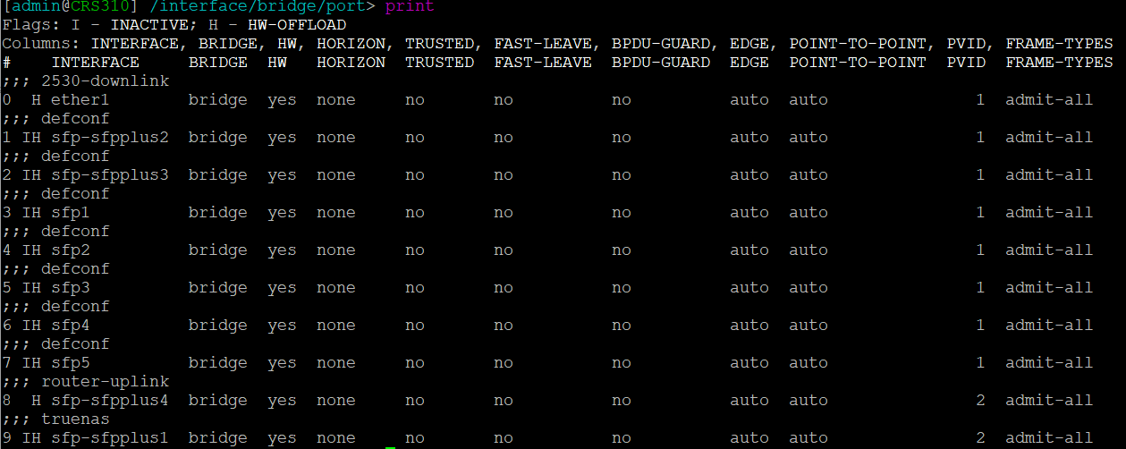
A default configuration will probably have been applied that defines a bridge with all ports added and a default IP address assigned to the bridge for initial remote config. To change a variable of an existing config line use the set command. You need to know the index number, starting at 0. To get this use the print command when in the appropriate context. For example below is the print output from the /interface bridge port context. Based on this, to change the PVID to 99 on port SFP1 use the command: set 3 pvid=99
The Config
This is a simple config with three VLANs: 2 (Management), 3 (IOT), and 10 (WLAN). The management VLAN is untagged on some ports, there is an SVI/VLAN interface with an IP address used for switch management. The other VLANs are tagged. Not all ports are in use and though they are added to the bridge and enabled, there is no VLAN config applied.
The following actions need to be performed:
- Create a bridge – the first bridge will refer to the switch chip (if available) do not create additional bridges as these will be in software, switching traffic through the CPU
- Assign ports to the bridge
- Create VLANs in the bridge & assign to ports as tagged or untagged as required
- Create a VLAN interface for management
- Assign an IP address to the management VLAN interface
- Ensure VLAN filtering is enabled on the bridge
- Set the PVID/native VLAN on ports as required
Create/edit a bridge (note this was done by autoconf and edited with set 0 vlan-filtering=yes)
/interface bridge
add name=bridge protocol-mode=none vlan-filtering=yes
Assign ports – all ports are assigned to the bridge by defconf. You can either edit the existing entry or remove and add with the desired config. Here you can see sfp-sfpplus1 and 4 have been assigned a PVID of 2 – the default PVID=1 does not show in the config.
/interface bridge port
add bridge=bridge comment=2530-downlink interface=ether1
add bridge=bridge comment=defconf interface=sfp-sfpplus2
add bridge=bridge comment=defconf interface=sfp-sfpplus3
add bridge=bridge comment=defconf interface=sfp1
add bridge=bridge comment=defconf interface=sfp2
add bridge=bridge comment=defconf interface=sfp3
add bridge=bridge comment=defconf interface=sfp4
add bridge=bridge comment=defconf interface=sfp5
add bridge=bridge comment=router-uplink interface=sfp-sfpplus4 pvid=2
add bridge=bridge comment=truenas interface=sfp-sfpplus1 pvid=2
Create VLANs on the bridge (L2) and assign to ports as tagged/untagged. VLAN is tagged/untagged using a comma separated list of interfaces. Note the management VLAN is tagged to the bridge itself as well as any ports – this makes the VLAN available to the CPU
/interface bridge vlan
add bridge=bridge comment=management tagged=sfp-sfpplus3,ether1,bridge untagged=sfp-sfpplus1,sfp-sfpplus4 vlan-ids=2
add bridge=bridge comment=WLAN tagged=ether1,sfp-sfpplus3,sfp-sfpplus4 vlan-ids=10
add bridge=bridge comment=IOT tagged=ether1,sfp-sfpplus3,sfp-sfpplus4 vlan-ids=3
Create the VLAN interface/SVI – this is the layer3 interface for a VLAN. You need to define this in order to apply an IP address.
/interface vlan
add interface=bridge name=management vlan-id=2
Apply an IP address to the management VLAN interface. If you have a defconf IP address configured on the bridge you will need to remove this.
/ip address
add address=172.20.0.4/24 interface=management network=172.20.0.0
Lastly here’s a bit of general system config setting the hostname, DNS and NTP sync
/ip dns
set servers=172.20.0.1
/ip route
add dst-address=0.0.0.0/0 gateway=172.20.0.1
/system identity
set name=CRS310
/system ntp client
set enabled=yes
/system ntp client servers
add address=0.uk.pool.ntp.org
The one place I got stuck for longer than I’d like to admit was having to set a PVID in a different place to VLAN tagging. With this config structure I initially assumed setting a bridge VLAN as untagged on a bridge port would define that as the PVID for the port – it does not.
The complete config:
/interface bridge
add admin-mac=F4:1E:57:7C:3E:F0 auto-mac=no name=bridge protocol-mode=none \
vlan-filtering=yes
/interface vlan
add interface=bridge name=management vlan-id=2
/port
set 0 name=serial0
/interface bridge port
add bridge=bridge comment=2530-downlink interface=ether1
add bridge=bridge comment=defconf interface=sfp-sfpplus2
add bridge=bridge comment=defconf interface=sfp-sfpplus3
add bridge=bridge comment=defconf interface=sfp1
add bridge=bridge comment=defconf interface=sfp2
add bridge=bridge comment=defconf interface=sfp3
add bridge=bridge comment=defconf interface=sfp4
add bridge=bridge comment=defconf interface=sfp5
add bridge=bridge comment=router-uplink interface=sfp-sfpplus4 pvid=2
add bridge=bridge comment=truenas interface=sfp-sfpplus1 pvid=2
/interface bridge vlan
add bridge=bridge comment=management tagged=sfp-sfpplus3,ether1,bridge untagged=\
sfp-sfpplus1,sfp-sfpplus4 vlan-ids=2
add bridge=bridge comment=WLAN tagged=ether1,sfp-sfpplus3,sfp-sfpplus4 \
vlan-ids=10
add bridge=bridge comment=IOT tagged=ether1,sfp-sfpplus3,sfp-sfpplus4 \
vlan-ids=3
/ip address
add address=172.20.0.4/24 interface=management network=172.20.0.0
/ip dns
set servers=172.20.0.1
/ip route
add dst-address=0.0.0.0/0 gateway=172.20.0.1
/system clock
set time-zone-name=Europe/London
/system identity
set name=CRS310
/system ntp client
set enabled=yes
/system ntp client servers
add address=0.uk.pool.ntp.org